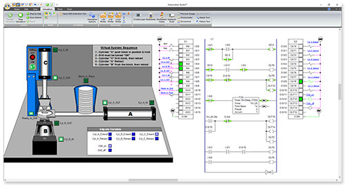


RSLogix uses "Drag and Drop" for placement of its commands and addresses, meaning to insert the command or address, simply click and drag it from the menu to the desired location, then drop it. The other side of each light is then connected to the PLC ports “OUT 0, 1, and 2”. The negative, black wire is connected to the PLC “COM 0 and 1” ports and connected to one side of each light.

Then the black wire coming from the power cord is connected to “VAC L2” and “VAC DC5” on the PLC and “N” on the Power Supply.įrom the Power supply the positive, red, wire is connected to the “VAC DC0, 1, 2, 3, and 4” ports on the PLC. To begin, start by connecting the PLC to power with L1, the white wire coming out of the power cord into the “VAC L1” port, and to the “L” Port on the power supply. Always unplug the circuit, disable the circuit breaker and verify that the circuit has been de-energized.įor this application, the full wiring shown in the picture above is not required, only the wiring described below. CAUTION: Never work on a live circuit, the AC line of the power is connected directly to the wall outlet and 110V, enough to kill a human or cause severe electrical burns including damage to internal organs.


 0 kommentar(er)
